
Noiseless at Last!
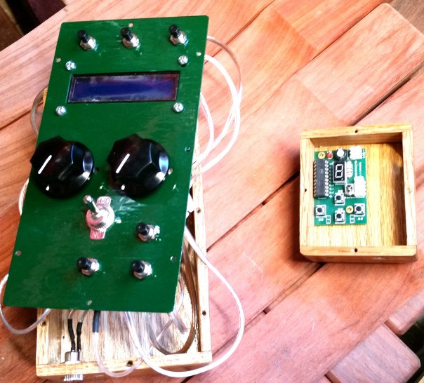
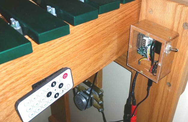
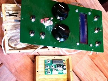
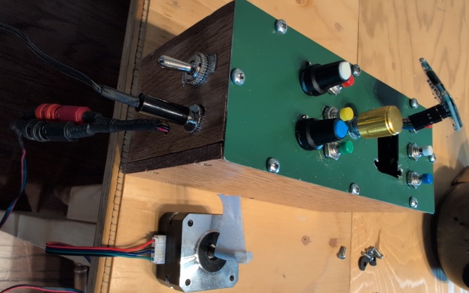
June 2018 was when this project really came together. Having essentially solved the two core problems — quiet motor drive and programmable control — it was time to build a proper control box worthy of the instrument. The new box was bigger than its predecessor, built from oak to match the vibraphone frame, and designed to house a much more complete set of controls.
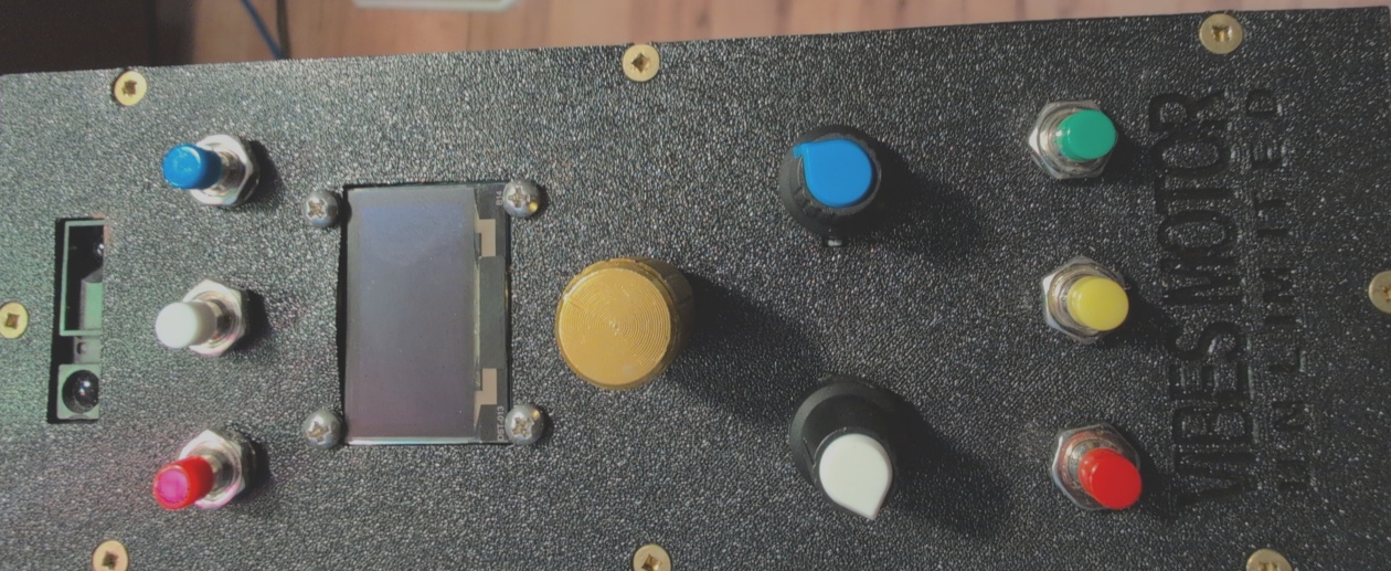
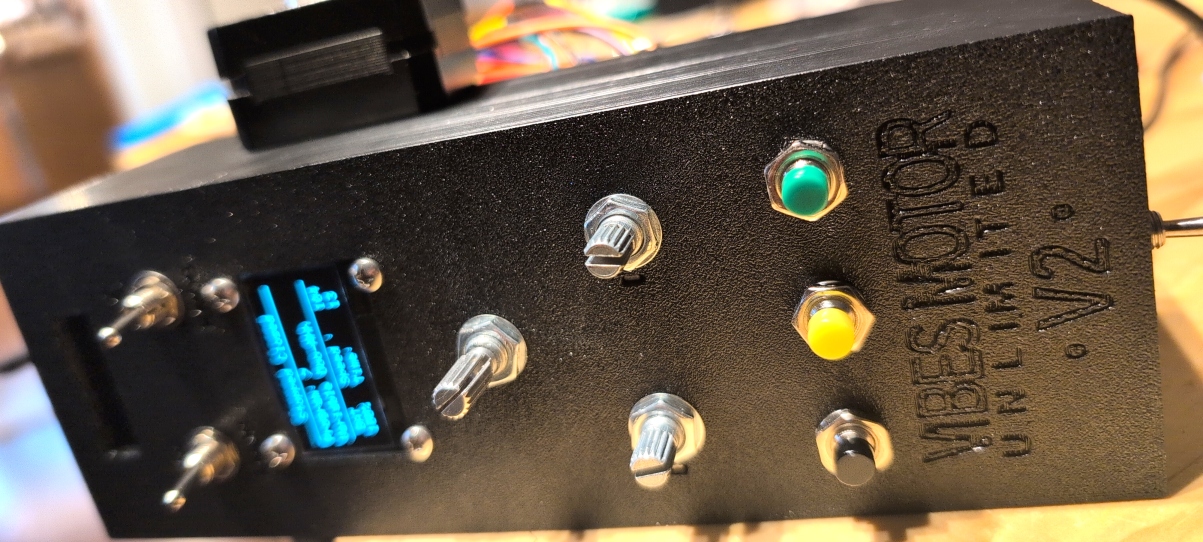
The faceplate carried two large potentiometer knobs — one for motor speed and one for parameters like vibrato depth — along with three buttons for motor run state: motor on, motor off with fans in the closed position, and motor off with fans open. Two further buttons toggled programs up and down, because by this point there were enough programs to navigate that a dedicated pair of buttons made real sense. A sixth button served as an Arduino reset. A power socket and switch were added, and I wired in a pair of RCA sockets so that the motor could be cleanly disconnected for transport without having to deal with any permanent wiring.
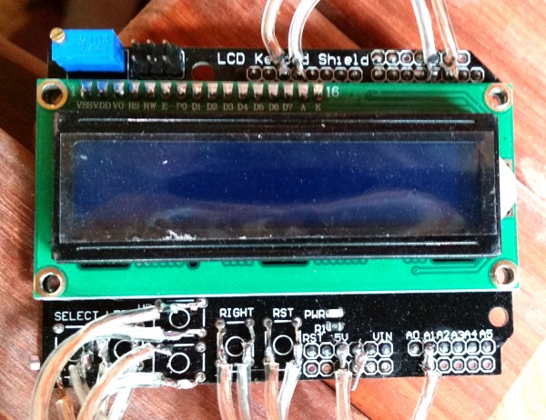
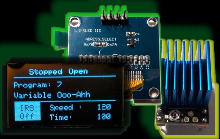
With so many more options than a conventional vibraphone motor, it became clear that some kind of display was essential — the user needed to be able to see at a glance what program was loaded and what state the motor was in. I chose an inexpensive LCD Keypad Shield that plugs directly onto the Arduino itself. It has its own row of buttons built in, which conveniently solved part of my input problem, though those buttons weren't really suitable for mounting on a faceplate. Instead I used external push buttons and soldered their connections directly onto the PCB of the LCD shield itself.
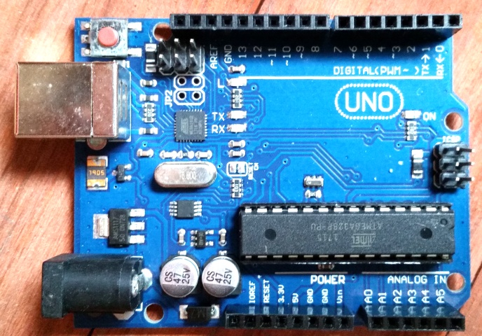
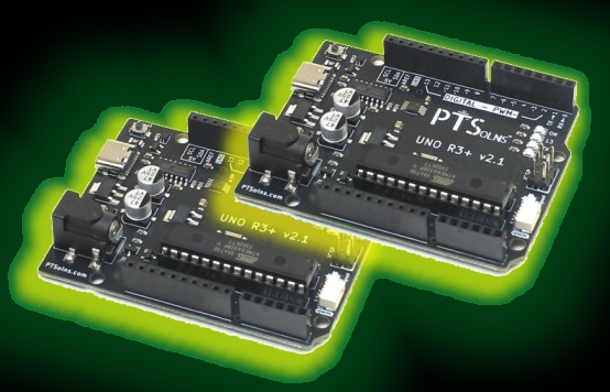
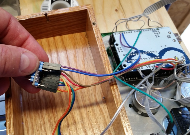
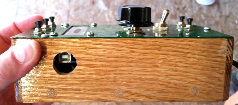
Because the Arduino's sockets were now occupied by the shield stacked on top, the regular breadboard jumper wires couldn't be used for anything else that needed connecting to the Arduino. Everything had to be soldered directly onto the back of the Arduino PCB. For programming access, rather than attempting to route an external USB socket, I simply drilled a hole in the side of the box directly in front of the Arduino's existing USB port — just large enough to insert a cable a few millimetres, giving full reprogramming access without ever opening the case.
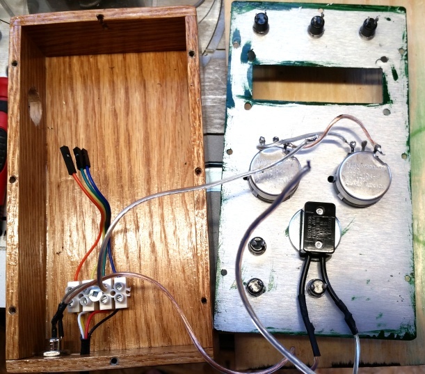
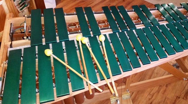
The faceplate itself was cut from thin aluminium sheet and painted in a glossy green to match the colour of the vibraphone. Getting everything mounted, wired, and fitting cleanly inside the oak case was satisfying work. A little additional code was needed to drive the display properly and to debounce the buttons so that programs didn't jump erratically when pressed — not a trivial problem with multiple inputs all being read in the same loop, but eventually sorted out to a workable standard.
The debouncing code deserves a mention too. Most debounce techniques involve introducing small fixed delays into the program timing — necessary to filter out the spurious rapid triggering you get from mechanical button contacts. The deeper issue though is structural: in a simple Arduino loop, the stepper motor can only be stepped once per full pass through the code, so any fixed delay — however small — directly interrupts that rhythm and can affect smoothness at higher speeds. A faster processor helps at the margins, but it doesn't solve the underlying problem. I got things running well enough, and I already had some ideas about how to address this more fundamentally — but that was a problem for another day.
The box was mounted on the vibraphone using Velcro, in a similar position to the original. It fitted well, though the location made the controls a little awkward to reach whilst playing, and the LCD display — which has a narrow viewing angle — sat low enough that reading it without bending down proved frustrating in practice. Not ideal for a working musician. These were things to think about for the future.
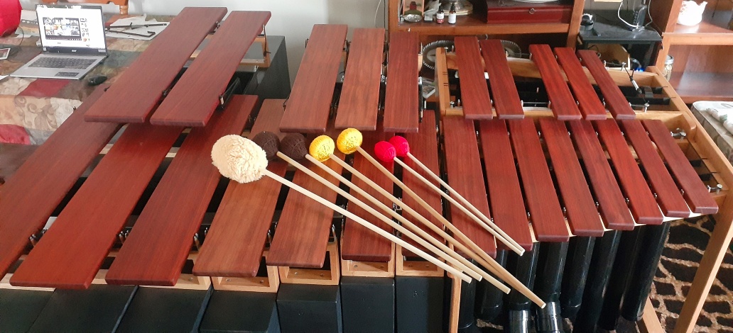
But there was still one significant problem to solve: belt noise. The toothed belt and pulley system had kept the fans perfectly synchronised, but it had introduced a new issue specific to the geometry of the vibraphone. The two resonator banks angle slightly towards each other at the small end of the instrument, which means the pulleys at the ends of those banks are not parallel to each other — or to the motor pulley driving them from below. The belt was therefore being forced to run at a slight angle, loading one side of the teeth more than the other, causing intermittent chatter as the teeth on the more loaded side slipped fractionally against the pulley.
I had noticed that some commercial vibraphones use a separate belt for each resonator bank rather than a single belt spanning both. With a smooth round O-ring belt this makes no functional difference, but once I saw it I immediately understood the solution to my noise problem. Two separate motor pulleys — one for each resonator bank — with two separate belts. Each belt would still connect a motor pulley to a resonator pulley that wasn't perfectly aligned with it, but each belt could simply twist slightly in its own direction to accommodate that misalignment, rather than being pulled out of plane by competing angles from both banks at once. No uneven tooth loading, no chatter.
Implementing this meant relocating one of the resonator pulleys. There was no room to shift anything on the naturals row, so the sharps row pulley was the obvious candidate — and conveniently, simply moving it to the other side of its bearing brought it into good alignment with the second motor pulley. The groove system along the tops of the struts that had previously guided the single belt became redundant, but that was a minor loss. The extended motor shaft needed to carry two pulleys side by side, and the second pulley sat far enough from the motor body that its belt exerted more leverage on the motor mounting — tending to pull the motor against its rubber suspension and allowing that second belt to slip slightly under load. A heavy rubber band tensioning the motor back in the other direction was an inelegant but effective temporary fix; good enough for now.

The result was transformative. At last — a fully functioning system that was genuinely quiet, properly synchronised, and capable of doing most of what I had set out to achieve. There were still a couple of things that nagged. The startup behaviour was one: every time you powered the unit on it simply resumed from whatever state it had been in when last switched off, meaning the fans could be in any random position. To have them correctly zeroed at startup you had to manually position them before running any motor program — an inconvenience that would have to be addressed properly at some point.
But those were problems for another day. For now, the V1.0 system was complete and working — and quiet. That was the headline.
Watch the video below to see the fully working V1.0 system