
Four Models Almost Done
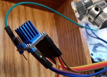
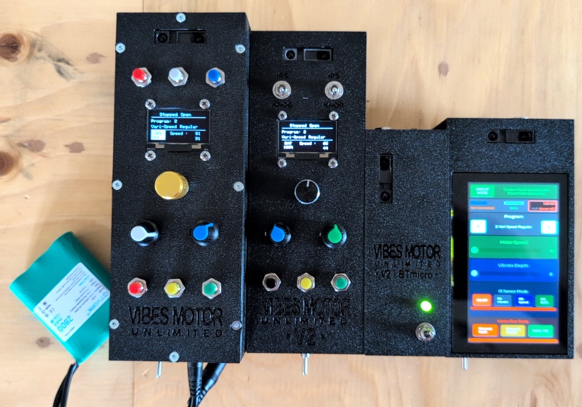
The start of April was productive — though a two-week personal trip sat in the middle of it all. Before leaving, the focus was on finalising the hardware decisions for all four versions of the control system. Every version drives the motor through the TMC 2209, but each has a different brain, feature set, and enclosure.
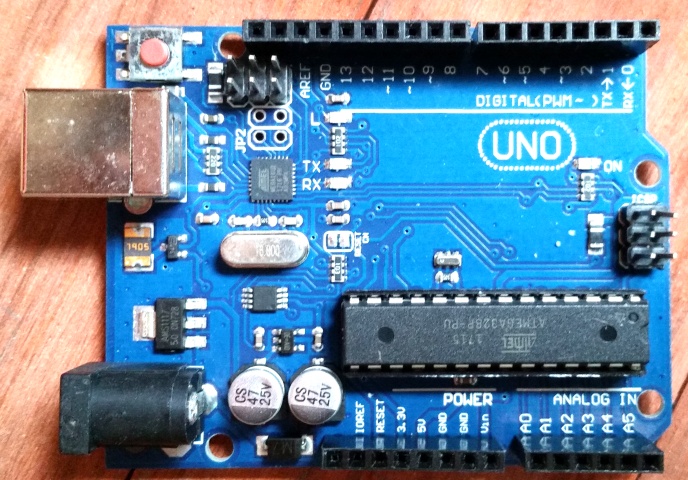
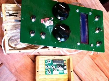
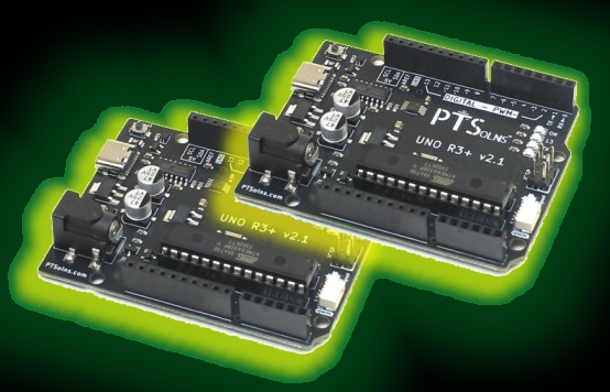
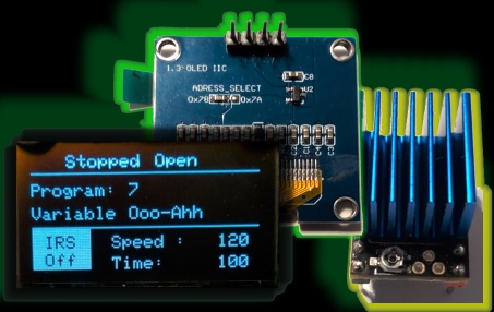
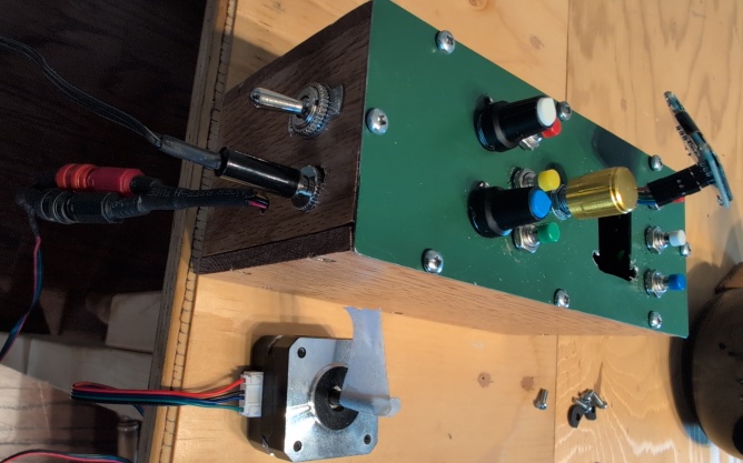
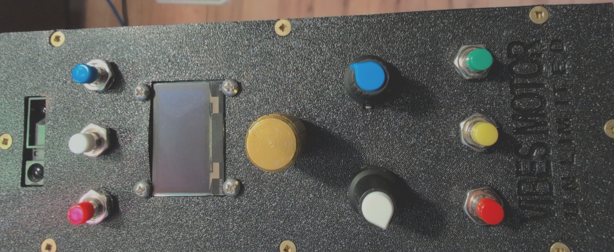
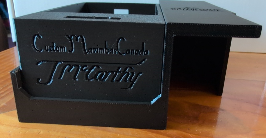
V1 was already complete and intentionally left unchanged — two Arduino Unos, the HC-05 Bluetooth module, OLED display, full physical controls, 3D printed housing with clip-on caddy, and an external 12V rechargeable battery. A sophisticated and capable system that could run for hours without mains power.
V3 had been well developed — great graphical interface on the Waveshare touchscreen, good housing and mounting clip. One unit was lost to a temporary wiring mistake, but a replacement was ordered and most hardware issues resolved before departure.
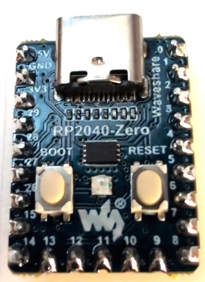
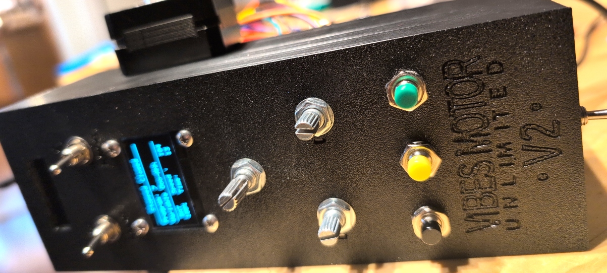
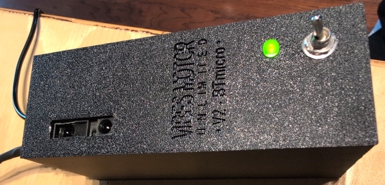
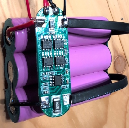
Work also began on V2, using the Waveshare RP2040 — smaller and faster than the Arduino Uno, capable of running the whole system from a single unit. Two variants were planned. The standard V2 would mirror V1 in capability — OLED display, physical controls, battery built into the box — but more compact. The V2BT special version would strip away all physical controls entirely, making it a tiny Bluetooth-only unit controlled exclusively through the phone app, with a single 18650 cell built in to keep the size right down.
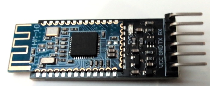
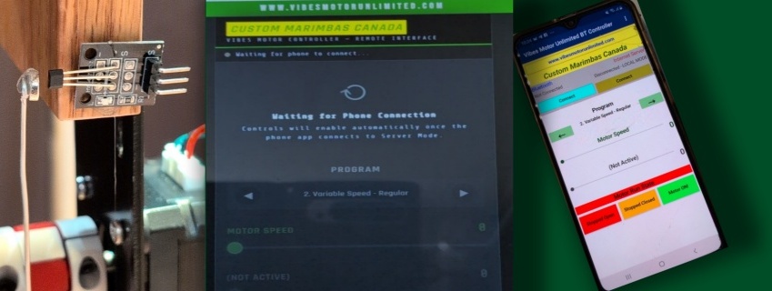
Because V3 used a different Bluetooth protocol to the HC-05 in V1, a modified version of the phone app had to be written. That led to choosing an improved Bluetooth module for V2 as well — matching the newer protocol. With the upgraded hardware also came an improvement in how the phone app communicated: rather than just sending data one way, it could now receive data back from the control box too. Any changes made on the physical controls would be reflected on the phone app in real time — a meaningful step up in polish.

The RP2040 also presented a challenge: not enough analogue inputs to support the infrared controller... but because the two controllable variables would only ever be controlled by the knob OR the IR sensor, I decided a solution might be to use a simple toggle switch to switch the input between potentiometer and IRS. The problem with this was that the software needed to know which state the switch was in - both for bluetooth communication with the phone app, and because the voltage needed to be interpreted differently with the IRS than with the potentiometer. Eventually the final solution was very simple - use double pole switches... There was plenty of spare digital inputs left on the RP2040 so the other pole of each switch was set to pull a pin to ground creating a matrix of 4 possible IRS conditions between the two pins. This sparked a realization that I could include a BOTH mode for the IRS where it was controlling both variables at once! This was even better than the original three-button configuration. Simpler to use and with an extra feature!
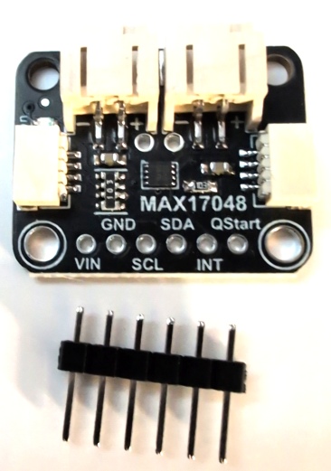
One RP2040 was lost to experimentation, but replacements were ordered and hardware sorted before the trip. During the trip itself, the phone app was rewritten to include the new IR switch options, and the internet control interface was updated to match. I would have to update the V3 software also when the time came. Because V2 and V3 versions had batteries built in, I decided it was important to be able to monitor charge, so V2 code was changed to add battery charge display on the OLED and both V2 and V3 code was updated to send the info through bluetooth also - phone app updated to include a battery display received through bluetooth. The actual battery monitoring would be done with a small board designed for this - the MAX17048 battery fuel gauge - that could be easily added to the I2C communication chain already in use on the RP2040.
By the time the trip was over, all the newly ordered hardware had arrived. Everything just needed to be wired up properly and tested. Four versions of a motor control system, each with its own character and use case — all sharing the same core motor driver, the same fundamental architecture, and the same phone app. Almost done.