
Let's Get Motoring!
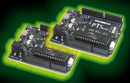
The new year arrived and with it a satisfying realisation: all the individual pieces were working. The components had been tested, the code had been written and proven for each part in isolation, and the two-Arduino architecture had been confirmed as solid. It was time to stop experimenting and start building. Time to put it all together — and make it genuinely great.
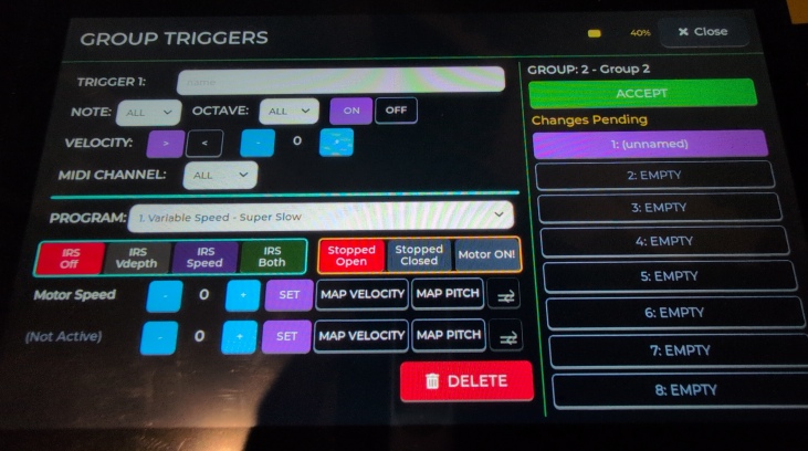
The first task was sitting down and planning the full library of FX programs. Not just the basic vibrato that any motor system can do, but a real set of effects worth having — interesting algorithms with genuine musical utility. Several new ideas were designed and coded: speed ramps, rhythmic patterns, asymmetric modulation shapes, auto-fade sequences. The kind of thing that makes a performer stop and think about what a motor system could actually do in a piece of music.
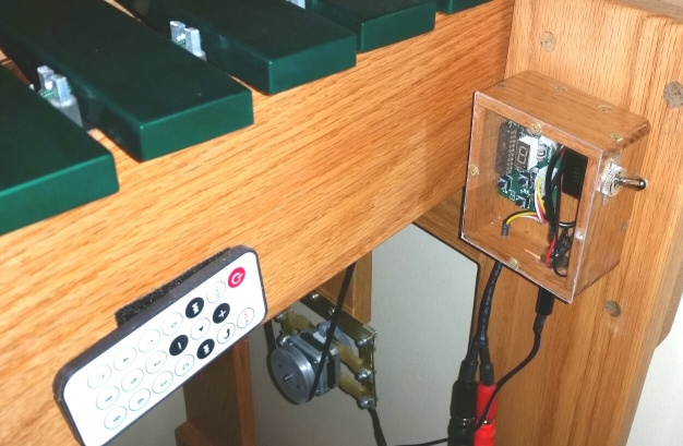
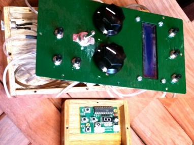
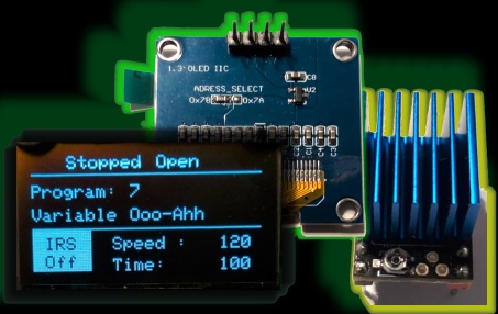
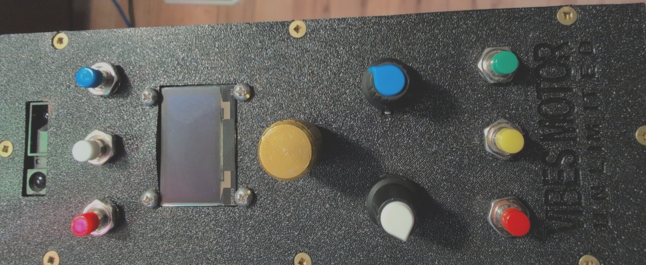
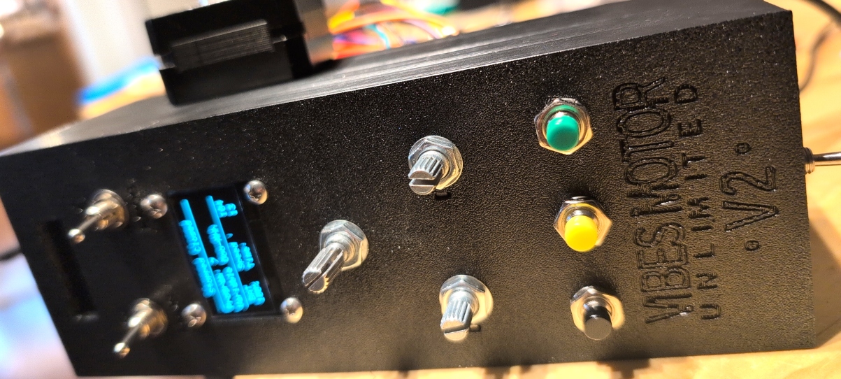
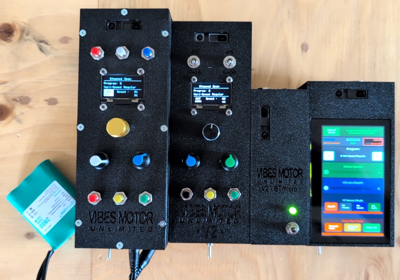
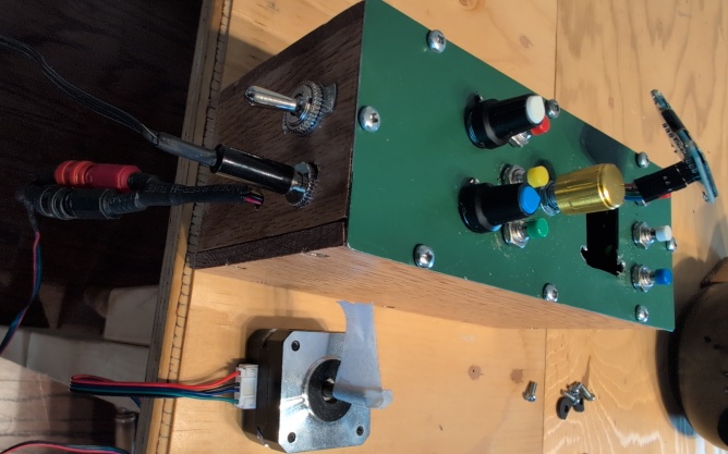
With the software taking shape, attention turned to the control box itself. The enclosure was made, the components were mounted, and everything was wired properly — not the temporary bench wiring of the testing phase, but real, permanent connections laid out with an eye to reliability and serviceability. The two potentiometers, the push buttons, the rotary encoder, the OLED display — all finding their final positions.
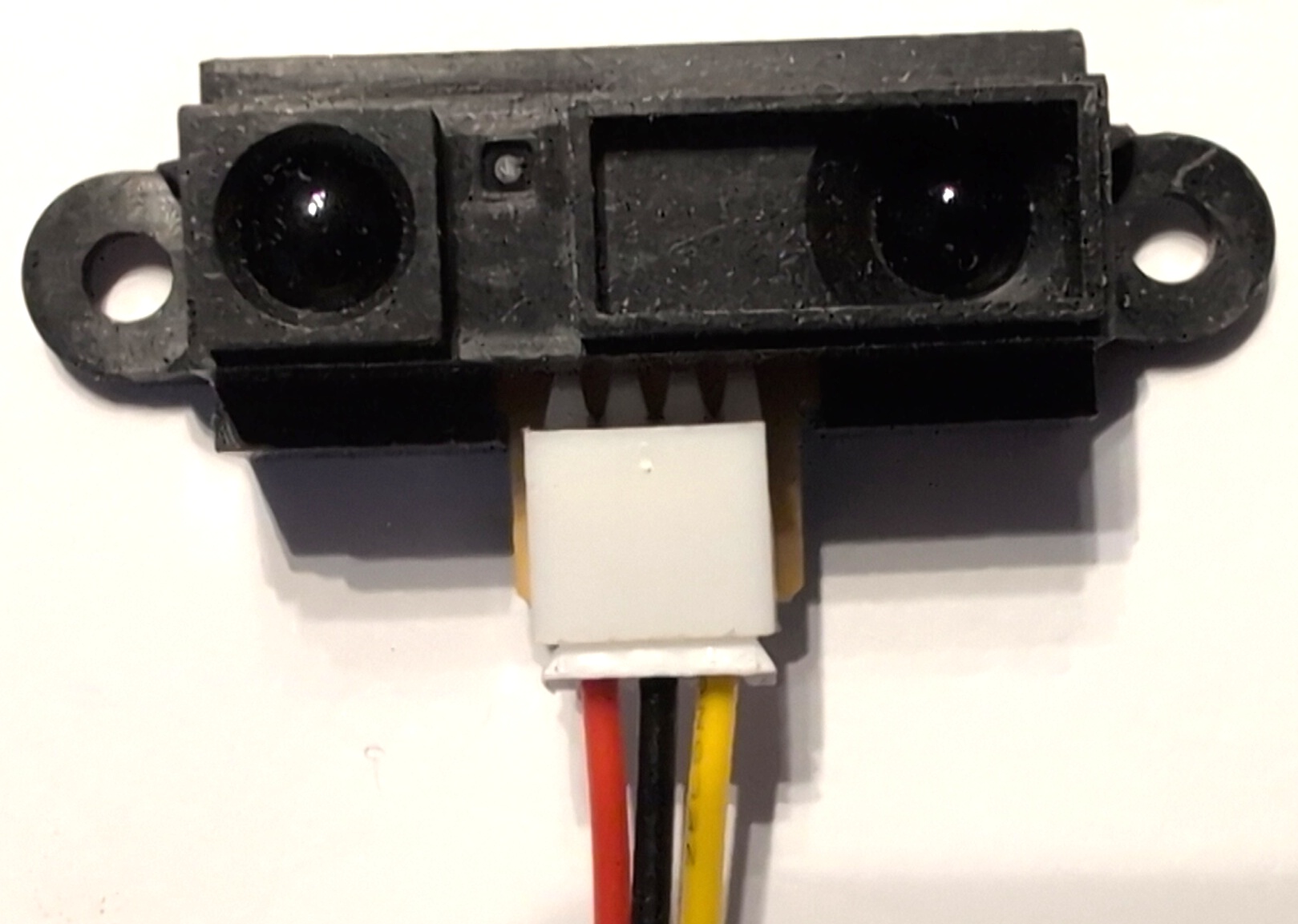
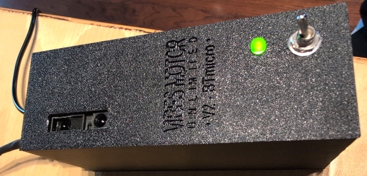
One of the most satisfying additions at this stage was getting the Sharp infrared distance sensor working properly. This small device measures the distance to whatever is in front of it — a hand, a mallet, any object — and returns an analogue voltage that the Arduino can read and act on. Getting the code right took some effort: the sensor's output is non-linear and needs calibration, and the readings needed smoothing to be useful as a musical control. But once it was dialled in, the result had real cool factor. Completely touchless control — wave a mallet above the sensor and the motor responds. To make it practical rather than just a novelty, three buttons were added to the interface: one to turn it off entirely, one to assign it to replace the function of the first potentiometer, and one for the second. Flexible, unobtrusive, and genuinely useful.
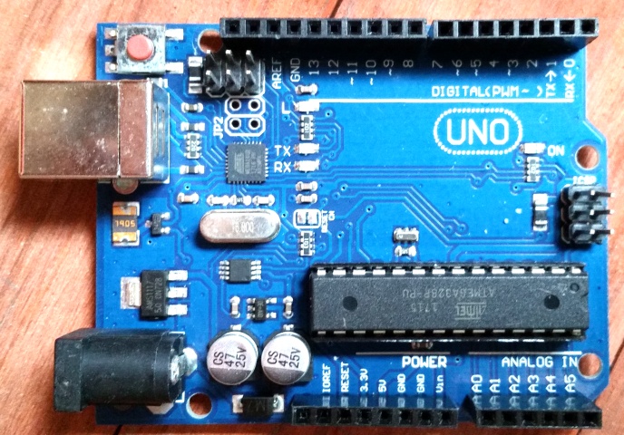
Then came the moment of truth — connecting the two Arduinos with the serial wires and running the whole system together for the first time. Things worked. Not perfectly, not immediately — there were code adjustments needed on both sides to ensure that neither Arduino's timing caused problems for the other — but the fundamentals were sound. The system talked to itself, the motor responded to the controls, the display showed what it should. It was a real system at last.
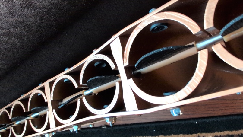
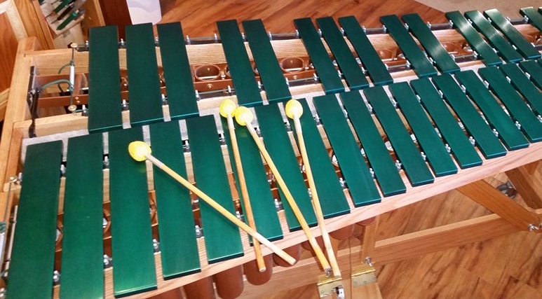
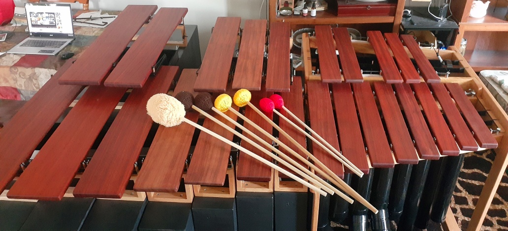
The other major work of this phase was entirely mechanical: a full upgrade to the physical fan and resonator system on the Masterclass Vibes. The original fasteners holding the resonator assembly together were replaced with a cleaner solution that intruded less into the tube space — important because the fans sweep through that space and any obstruction risks contact and noise. Tiny ball bearings were fitted to the various shaft contact points throughout the assembly, keeping motion smooth and silent with no friction at those junctions.
New shafts and fans were made from scratch. The original sheet aluminium butterfly fans were replaced with a new design: rubber fans, symmetrical and properly balanced, but — crucially — adjustable after installation. If anything ever did make contact during motion, rather than a loud metallic click, the rubber would simply flex and allow the motion to continue with a much softer sound. A significant improvement in both performance and peace of mind.
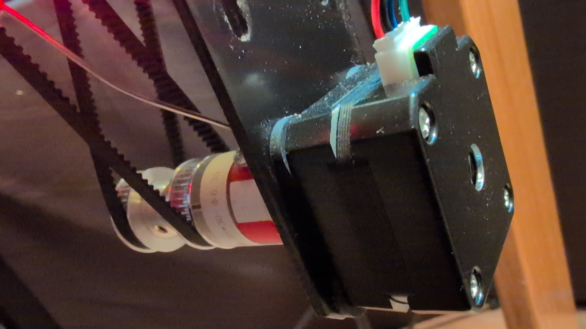
The motor itself was mounted using an off-the-shelf bracket with rubber isolation washers — providing vibration damping while keeping the assembly rigid enough that the motor shaft stayed true and both belts maintained consistent tension. A rubberised spider shaft coupling connected the motor to the pulley shaft: forgiving enough to accommodate small mounting angle errors, but firm enough to transmit motion accurately. And with one more layer of vibration isolation between motor and belts, the whole mechanical system became quieter still.
I now had a working motor system. Still a few things to sort out — but running, responsive, and quiet. The V2.0 build was real.